Plastics in Packaging magazine published my new article on the history of thermoform tooling in its 20th Anniversary Special Supplement. This supplement is not available online for free, but I received permission from the editor to post my article here. Continue below to learn how thermoformed packaging was manufactured before machines and computers talked to each other.
Art history teaches us that nothing exists in a vacuum; when comprehending, one must understand the larger trends of the society in which it was created. Thermoform tooling has evolved drastically over the last 50 plus-years. As with art, the technology of thermoforming needs to be put in its historical context to provide an accurate portrait of how vast shifts in manufacturing and engineering created the landscape where thermoforming could participate—and help define—the expectations of the time.
1960s
In the 1960s, the way products were merchandised changed from being sold at mom-and-pop shops to being packaged for retail display at ‘big box’ stores. The need for visual packaging that showcased the product, while offering pilferage protection, created the need for clamshell and blister packaging. Yet, making a mold on which the plastic package could be formed did not come easy; to do so, one must have had access to a pattern maker and a foundry.
Pattern makers were people who took the physical product to be packaged and handmade—out of a combination of wood, wax, clay, plaster, and epoxy—the product cavity for the foundry to pound into sand and then pour molten aluminum into to create the prototype mold. Once the prototype was approved, the pattern maker would duplicate into a row, mount to a match plate, and return to the foundry to cast. Rinse and repeat until you had a multiple-cavity production tool, which was then polished, drilled, tapped, and mounted. After the first plastic sheet had been vacuum formed over the tool, it was sent to a die maker who would hand-gig the board and hand bend the rule.
1970s
In the 1970s, the industry evolved from heat-sealing plastic blisters by hand to auto feeding; this required a higher level of blister quality and die cutting consistency to provide a stable flange upon which the card could be sealed. The current method of sand casting was inherently inconsistent, because sand isn’t a complete solid; it would move unpredictably around the pattern. Variations in each casting, and therefore each cavity, were but one of the many challenges to making a tool that met the quality requirements of blister auto feeding equipment.
The proliferation of copying mills throughout industry then allowed the cavity mold to be machined directly into a block of aluminum, instead of being sand casted. Copying stylists were essentially joysticks attached to the milling machine for the operator to control with left-to-right and up-and-down motion. Instead of manually spinning wheels for the end mill to cut on the x and y-axis, tracers gave the operator more control over the movement of the end mill cutting the tool.
While tracing mills allowed for a more realistic shape when compared to casting, each cavity was still done one-at-a-time and by hand, with the operator visually referencing the original mold model and copying the shape in aluminum. The quality of the tool was therefore dependent on the sculpting skills of the operator and the ability to master the movements of the milling machine.
Once you were able to more accurately produce the cavity shape, die builders were able to make a more consistent die-cut product; this allowed for integration with auto-feeding blister equipment.
In the late 70s, tracing mills that ran automatically became accessible to vacuum formers. Here, the stylist used sensors to orient the positioning of the end mil over the aluminum block based on the corresponding model mold.
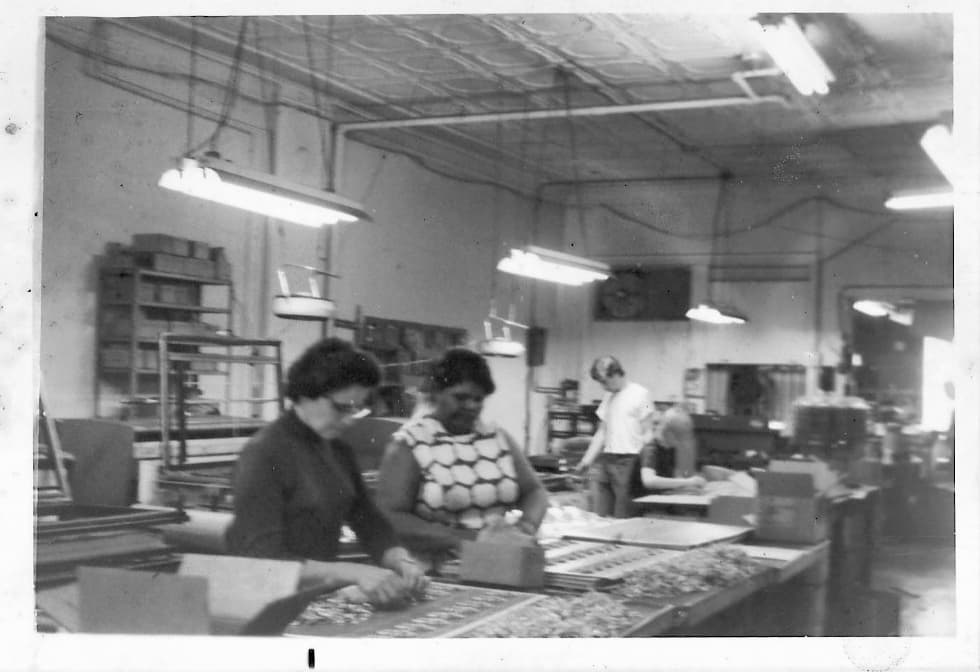 Above: Dordan CEO/President, Daniel Slavin, pictured in white tee at Dordan in Chicago, circa. 1974.
1980s
From the 1960s through the early-1980s, vacuum form tools were machined, not engineered. The scale began to tip towards engineering in the mid-1980s, when drafters drew, essentially, blue prints of the package for the machinist to use to mill the tool. Engineers used calipers to measured the product and draft the rudimentary dimensions for the machinist to reference, instead of a model mold. This shift required machinist to be able to interpret 2D drawings to produce a 3D tool. As with pattern makers that made the model mold, engineers used craft and the tools available at the time to replicate the geometry of a physical product to create the tool on which the package could be formed.
In the late 80s, the rise of computers and the ability to program machines fundamentally changed the way tooling was made. Instead of drafters creating drawings of the model for the copying stylist to replicate, engineers could develop the packaging dimensions on a computer that the machinist could use to mil the tool. It was around this time that CNCs became available, such that the tool paths of the 2D CAD design could be programed into the CNC to automatically cut the tool. However, this software could only produce designs on the x and y-axis. To machine the z-axis, therefore, calculations had to be determined independent of the software to program the CNC to cut.
%20compressed%20again.jpg?width=500&name=staying%20in%20shape%20is%20a%20matter%20of%20form%20(1)%20compressed%20again.jpg)
Above: Dordan print advertisement in Packaging World, mid-1980s
1990s
In the early 1990s, engineering software progressed from generating 2D designs to 3D models. This generated all of the dimensions necessary for the CNC to automatically cut the tool and eliminated the guesswork associated with determining this dimension in a language that the CNC could understand.
2000s
In the early 2000s, modeling softwares began to speak directly to CNCs, further reducing the role of machinists in making tooling. CNC operators received the fully engineered tool paths generated from the CAD/CAM program to input into the CNC. Thus the production of tooling became much more efficient, because there was a direct integration between the design of the part and the machining of the tool.
Today
This approach to making thermoform tooling via CAD CAM/CNC integration continues today, with sizable gains in modeling softwares and machining capabilities. Still, thermoform engineers must have a fundamental understanding of the technologies at their disposal to create a tool that allows for consistent and high quality thermoforming. Like pattern makers and copying stylists, today’s engineers use expertise of skill to manipulate 3D models in order to create a tool off which a part can be formed.
Brooklyn, New York-based artist, Dana Bell, used algae-plastic supplied by custom thermoforming company, Dordan Manufacturing, to vacuum form shapes as interpretation of the dynamic between material, man, and machine. Using the most basic tools of vacuum forming—material and mold—Bell illustrates how the evolution of industry is the result of skillfully manipulating the materials and tools of the society in which it is created.
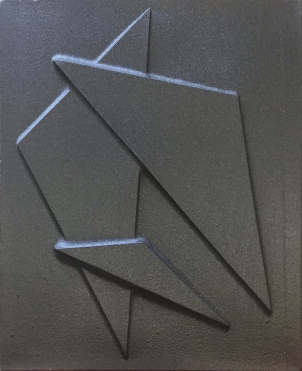
Thermoformed algae plastic art by D. Bell
Dordan Manufacturing is a designer and manufacturer of custom thermoformed packaging, since 1962. Family-owned and operated, Dordan is based in Woodstock, IL, about 60-miles NW of Chicago.